5 Empirical foundations
Part II — The Second Law
Last updated: 25-05-2026
5.1 Introduction
Consider the free expansion of a gas into a vacuum. At the microscopic level, the gas consists of a large number of particles interacting through forces that depend on the distances between them. When the partition separating the gas from the evacuated half of the container is removed, the particles spread throughout the whole volume.
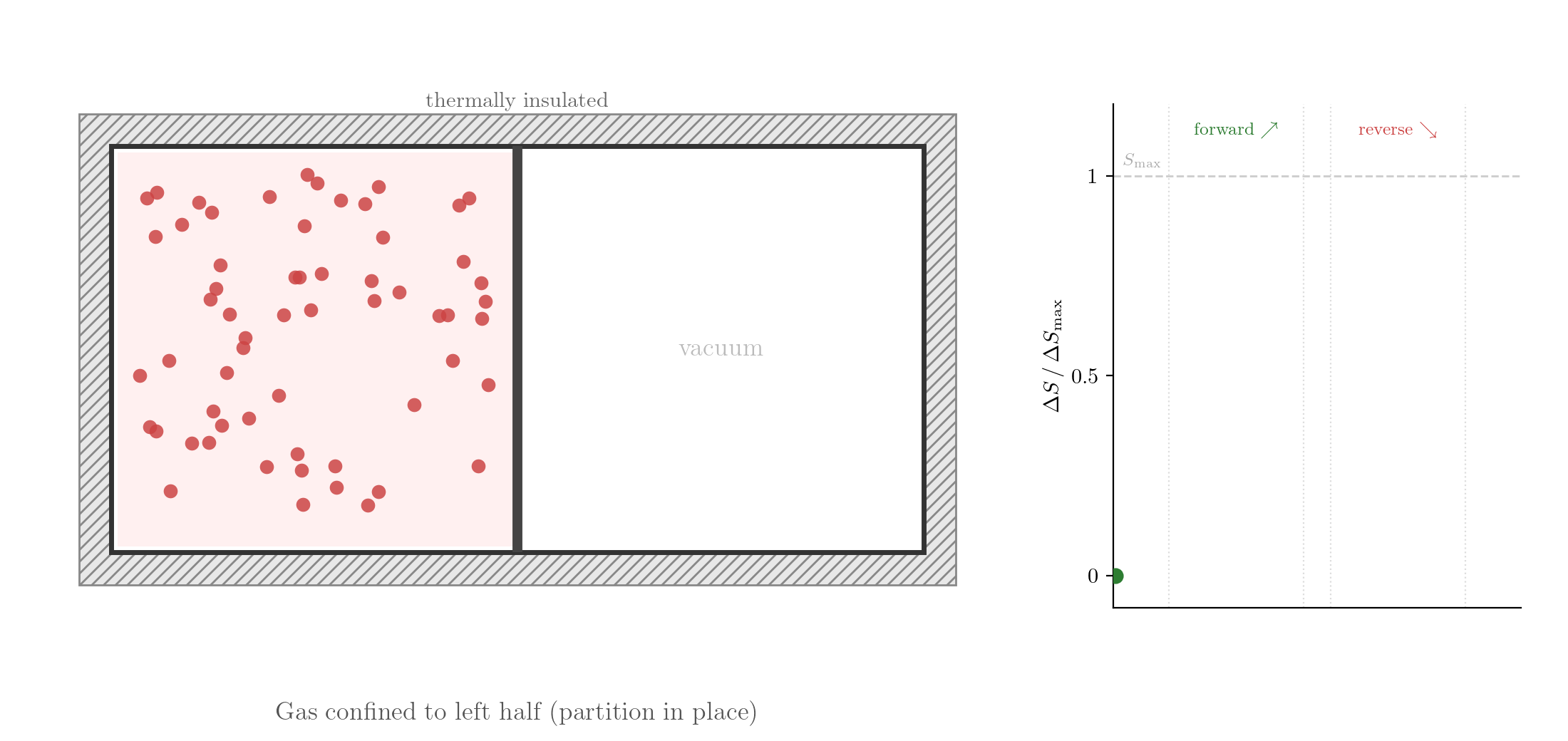
The reversed process is consistent with Classical Mechanics: take the final state, reverse the velocities of all particles, and let the system evolve. Since the equations of motion are symmetric under time reversal, the particles would retrace their trajectories exactly and the gas would spontaneously contract back into the left half. Yet this never happens. If you watch such a process in a film and see the gas contracting, you know the film is running backwards. The evolution of thermodynamic systems is not invariant under time reversal.
It is often said that the Second Law of Thermodynamics defines the arrow of time. This is not entirely accurate. Irreversibility is already embedded in the foundational assumptions of thermodynamics: a system that is left undisturbed tends towards equilibrium and, once there, does not spontaneously leave it. This is our starting point, not a theorem derived from the Second Law.
What the Second Law does is go much further: it determines precisely which processes are physically possible and which are not. Free expansion is one instance of a broad class of processes with a definite natural direction:
- heat flows spontaneously from hot to cold, never in reverse;
- two gases mix spontaneously and do not unmix;
- mechanical energy dissipated by friction appears as heat and cannot be fully recovered as mechanical energy.
Energy conservation alone permits each of these processes to run in either direction. The Second Law selects the direction.
5.2 Some useful definitions
Before formulating the Second Law of Thermodynamics, we will introduce some definitions that will be useful in the remainder of this lecture and in the next one.
5.2.1 Reversible processes
A thermodynamic process is reversible if it can be carried out in the opposite direction so that the system retraces the same sequence of states in reverse order and the surroundings are exactly restored to their original condition, that is, no net change is left anywhere in the universe. All processes that fail this criterion are irreversible.
Quasi-static execution. The process must be performed so slowly that the system remains in equilibrium at every instant. A rapid process leaves the system in a non-equilibrium state; the intermediate configurations are not thermodynamic states and cannot be retraced.
Absence of dissipation. Friction, viscosity, electrical resistance, and all similar effects convert ordered mechanical energy irreversibly into heat. They must be absent from the system, but also the surroundings. Even a quasi-static process subject to friction is irreversible.
One of the peculiarities of thermodynamics is that irreversible processes are the rule rather than the exception: real processes are always irreversible to some degree. Reversible processes are limiting idealizations; they represent the best performance achievable in principle, and real processes approach them as dissipation is reduced and execution is slowed.
The thermalization process of two systems, i.e. the process under which the two systems in thermal contact reach thermal equilibrium by spontaneous flow of heat, is irreversible. This follows from the general principles discussed in Section 2.2.2.
5.2.2 Thermal reservoirs
A thermal reservoir or, simply, reservoir is an idealized system in thermodynamic equilibrium defined by two properties: (1) it can exchange heat with the surroundings but no work, (2) its temperature does not change when any finite amount of heat is exchanged with the surroundings. This is an idealized system, in the sense that it cannot be realized exactly in the lab, but it can be approximated arbitrarily well. An ideal gas with an extremely large fixed volume in thermodynamic equilibrium is a good approximation of the reservoir: when it exchanges heat with the surrounding its energy varies by very little and so does its temperature. When the system is made larger and larger, the change in temperature can be completely neglected. A reservoir is characterised completely by its temperature.
Thermal reservoir — an idealized system that exchanges heat but no work with its surroundings, with temperature fixed regardless of how much heat is exchanged.
5.2.3 Cyclic machines
A process is called cyclic if it returns the system to its initial state. For instance, we can compress a gas and then expand it back to its original volume, or we can heat a liquid and then cool it back to its original temperature. In a cyclic process, the system starts and ends in the same state, but it may exchange energy with the surroundings and it may produce net effects on the surroundings.
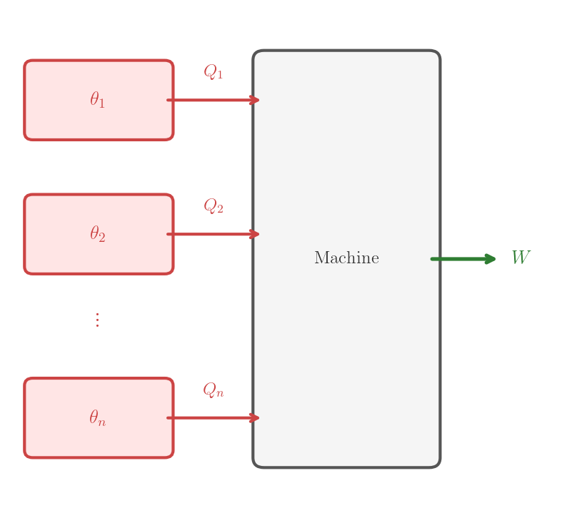
A thermodynamic machine is any thermodynamic system which undergoes a given, well defined, process. During this process, the system is able to exchange work with the environment and heat with \(n\) systems initially in thermodynamic equilibrium with temperatures \(\theta_1, \theta_2, \ldots, \theta_n\). The thermodynamic machine is defined by the system and the process. Since we will consider here only thermodynamic machines, we refer to them simply as machines. A machine is said to be cyclic, resp. reversible, if the process it executes is cyclic, resp. reversible.
Cyclic machine — a thermodynamic system executing a cyclic process, exchanging heat with one or more systems and work with the surroundings.
In general, the temperature of the systems with which the machine exchanges heat may change during the process. In theoretical arguments, one is often interested in machines that exchange heat with reservoirs, whose temperature does not change during the process by definition.
5.3 Second Law of Thermodynamics
P 5.1 (Clausius’s statement of the Second Law) A cyclic machine that transfers heat from a colder system to a hotter one without any other effect on the surroundings is physically impossible.
The fact that the cyclic machine has no other effect on the surroundings means that it does not exchange work with the surroundings and does not exchange heat with any other system.
Cyclic machines that exchange heat with only two systems and transfer heat from the colder to the hotter one are called refrigerators or heat pumps. The Second Law states that refrigerators that operate without exchanging work do not exist.
We know already that heat does not flow spontaneously from a colder system to a hotter one when the two are placed in thermal contact (see Consequence 3.4). The Second Law goes much further: it states that no cyclic machine can be built that forces heat to flow in that direction without any other effect on the surroundings. This is a much stronger statement than the mere observation of the direction of spontaneous heat flow.
In the next sections we will investigate some consequences of the Second Law. In particular we will analyze cyclic machines which can exchange heat with one or two systems. We will see that, among all possible heat and work flows that are compatible with the First Law, the Second Law selects some of them as physically impossible.
5.4 Kelvin’s statement
C 5.1 (Kelvin’s statement) A cyclic machine that absorbs heat from a single reservoir and converts it entirely into work, with no other effect on the surroundings, is physically impossible.
This statement is the precise formulation of the idea that heat cannot be converted entirely into work, and it has very important practical consequences. For instance, we cannot build a power plant that produces electricity simply by absorbing heat from the environment, without any fuel or other energy source.
Before proving this statement, we need to introduce the cyclic dissipator: a particular cyclic machine that converts work into heat.
5.4.1 Cyclic dissipators
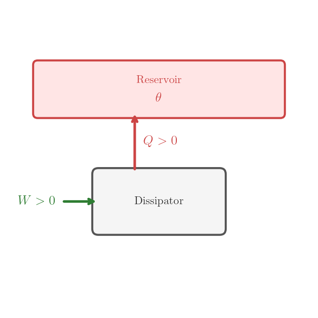
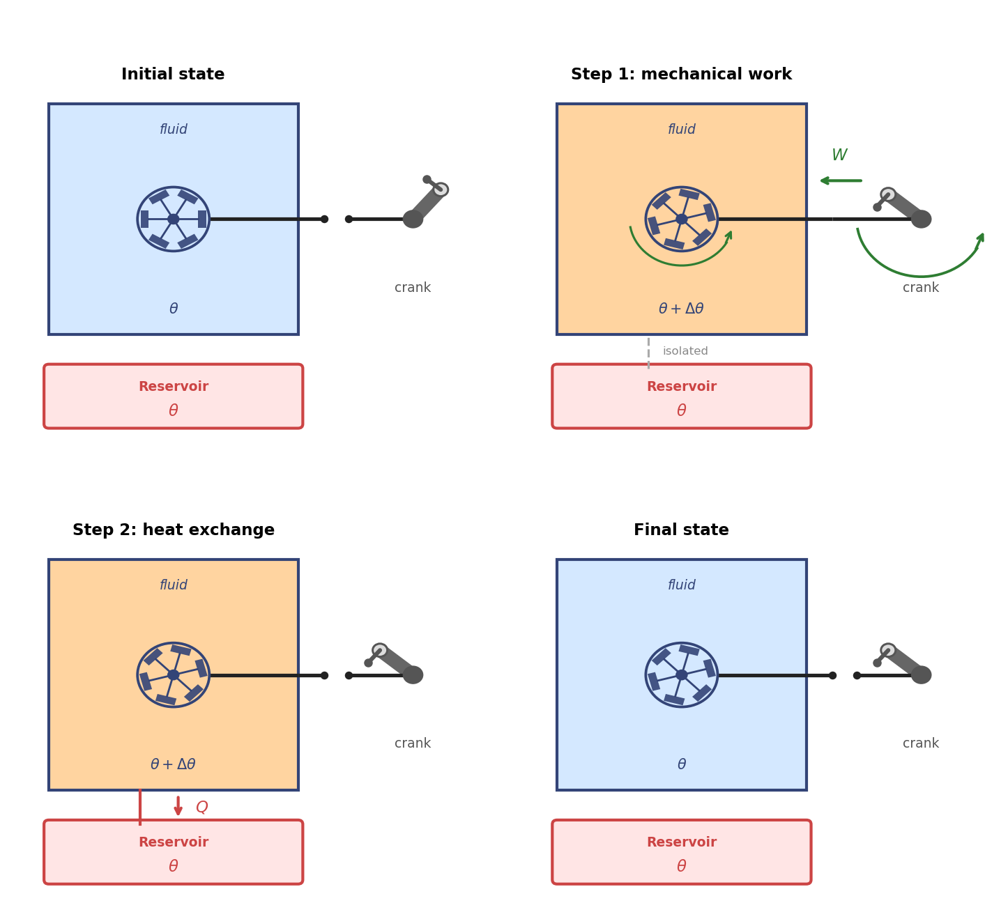
A cyclic dissipator is a cyclic machine that, in one cycle, consumes work \(W > 0\) from the environment and deposits heat \(Q = W > 0\) into a reservoir. A priori, it is not obvious that a cyclic dissipator exists that satisfies the inequalities \(W > 0\) and \(Q = W > 0\). We show the existence of such a machine by explicit construction.
Cyclic dissipator — converts work entirely into heat deposited into a reservoir: \(Q = W > 0\), no cold source required.
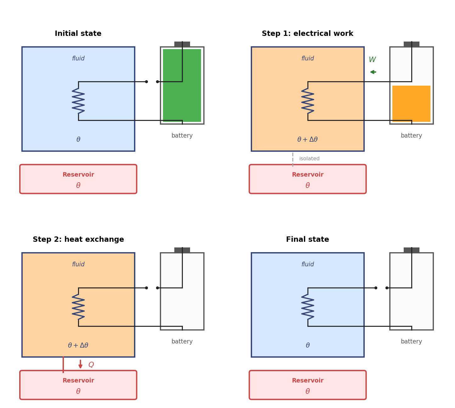
The construction of cyclic dissipators is straightforward. Consider a substance whose state is completely defined by pressure and volume, like a homogeneous liquid or gas. The substance is contained in a rigid bottle that can exchange heat with a reservoir at temperature \(\theta\). An electric resistance is immersed in the fluid and connected to a battery which is placed outside of the bottle. A switch is used to turn the electric current on and off. The machine starts from an equilibrium state at temperature \(\theta\) but it is kept isolated from the reservoir. Then it executes the following cycle:
The switch is turned on, the electric current flows and energy is transferred from the internal energy of the battery to the fluid by means of electric work \(W\), then the switch is turned off. The fluid is thermally isolated and no heat is exchanged with the reservoir. The fluid may not be in equilibrium in this process.
The reservoir is connected to the bottle and the fluid is allowed to exchange heat with it until it reaches thermal equilibrium at temperature \(\theta\).
At the end of this process the fluid has the same temperature and volume as at the beginning, so the machine is cyclic. The net work consumed is \(W > 0\) and the net heat released to the reservoir is \(Q = W > 0\), so the machine is a cyclic dissipator.
One can easily design also a completely mechanical cyclic dissipator, for example by using a paddle wheel immersed in the fluid and driven by a hand crank. The fluid is confined in a rigid bottle as before. The paddle wheel dissipates the mechanical work delivered by the hand into heat, which is absorbed by the fluid and then released to the reservoir.
5.4.2 Proof of Kelvin’s statement
The proof proceeds by contradiction: assume the negation of Kelvin’s statement and construct a process that violates the Second Law.
Assumption. Suppose Kelvin’s statement fails: a cyclic machine, in one cycle, absorbs heat \(Q > 0\) from a single reservoir at temperature \(\theta_2\) and delivers work \(W\) to the surroundings. Notice that the First Law implies \(W = Q > 0\). We’ll refer to this machine as Kelvin-violating machine.
Construction. Couple the Kelvin-violating machine to a cyclic dissipator that, in one cycle, absorbs the work \(W>0\) delivered by the Kelvin-violating machine and deposits heat \(Q = W > 0\) into a reservoir at temperature \(\theta_1 > \theta_2\). The combined machine is defined by the two machines together, executing their cycles simultaneously.
Contradiction. The combined machine is cyclic because both machines are cyclic. It extracts heat \(Q>0\) from the colder reservoir at temperature \(\theta_2\) and it delivers it to the hotter reservoir at temperature \(\theta_1\), with no other effect on the surroundings, violating Clausius’s statement (Principle 5.1).

5.4.3 Equivalence to Second Law
Kelvin’s statement (Consequence 5.1) can be shown to be equivalent to Clausius’s statement (Principle 5.1). In fact, in many textbooks, Kelvin’s statement is provided as the definition of the Second Law, and Clausius’s statement is derived from it. We have chosen here a different approach, and we will comment on the equivalence of the two statements later on.
5.5 Heat engines and refrigerators
Two kinds of cyclic machines are of particular importance to derive the consequences of the Second Law: heat engines and refrigerators.
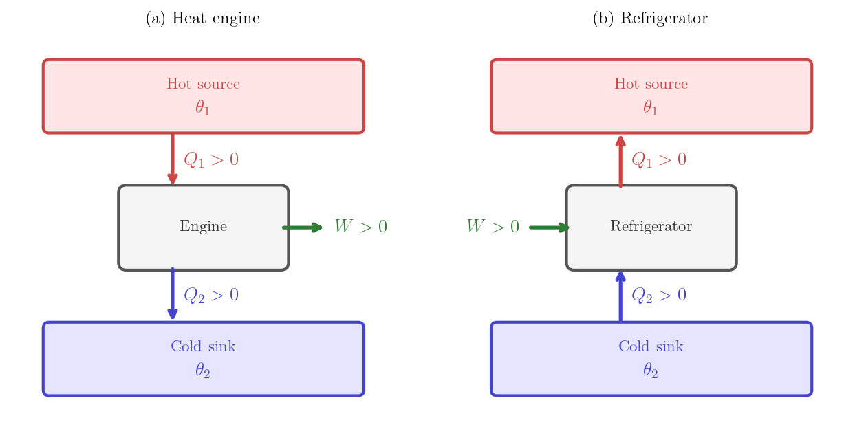
A heat engine is a cyclic machine that, in one cycle, absorbs heat \(Q_1 > 0\) from a hot thermal reservoir at temperature \(T_1\), delivers net work \(W > 0\) to the surroundings, and releases the remainder \(Q_2 > 0\) to a cold reservoir at temperature \(T_2 < T_1\). With these conventions, the First Law requires \(-W + Q_1 - Q_2 = 0\), i.e. the heat released to the cold reservoir is \(Q_2 = Q_1 - W\).
Heat engine — absorbs \(Q_1\) from a hot reservoir, delivers work \(W\), releases \(Q_2 = Q_1 - W\) to a cold reservoir.
The thermal efficiency of the engine is defined as the fraction of the absorbed heat that is converted into work:
\[\eta = \frac{W}{Q_1} = 1 - \frac{Q_2}{Q_1}. \tag{5.1}\]
Thermal efficiency — \(\eta = W/Q_1 = 1 - Q_2/Q_1\).
A refrigerator is a cyclic machine that consumes work \(W > 0\) to extract heat \(Q_2 > 0\) from a cold reservoir and deposits \(Q_1 > 0\) into a hot reservoir. With these conventions, the First Law requires \(W + Q_2 - Q_1 = 0\), i.e. the heat released to the hot reservoir is \(Q_1 = W + Q_2\).
Refrigerator — consumes work \(W\) to extract \(Q_2\) from a cold reservoir and deposit \(Q_1 = W + Q_2\) into a hot reservoir.
A real-world example of a heat engine is the Stirling engine. The following video shows a working model of a Stirling engine, illustrating the cyclic nature of the process and how heat from a hot source is converted into mechanical work.
For the generic machine represented in Figure 5.2, \(Q_i\) carries a sign: positive means absorbed, negative means released. Different sign conventions are used for the specific machines and are reflected in the direction of the arrows in the figures:
- For the engine, \(Q_1\) and \(Q_2\) are defined as positive magnitudes. The engine is a special case of the generic machine with \(n=2\), \(Q_1^{\rm generic} = Q_1\) and \(Q_2^{\rm generic} = -Q_2\).
- For the refrigerator, \(Q_1\) and \(Q_2\) are defined as positive magnitudes. The refrigerator is a special case of the generic machine with \(n=2\), \(Q_1^{\rm generic} = -Q_1\) and \(Q_2^{\rm generic} = Q_2\).
5.5.1 The Carnot engine
A priori, it is not obvious that heat engines and refrigerators exist that satisfy the inequalities \(Q_1 > 0\), \(W > 0\) and \(Q_2 > 0\). We will construct one such machine, called the Carnot engine. We will use an ideal gas as the working substance, but the construction can be easily generalized to other working substances. The Carnot engine is a reversible machine. When operated in reverse, it works as a refrigerator. We will compute the efficiency of the Carnot engine and show that it depends only on the temperatures of the reservoirs.
The Carnot engine uses \(n\) moles of ideal gas as the working substance. The gas is enclosed with a piston which can be used to expand and compress the gas. We assume that the piston moves with no friction. The engine operates between two reservoirs at temperatures \(T_1\) and \(T_2\) with \(T_1 > T_2\). For simplicity, we will consider a constant adiabatic index \(\gamma\), but one should keep in mind that the following construction can be easily generalized. Notice that, since we are dealing with an ideal gas, it is natural to use the ideal-gas temperature (denoted by \(T\)) introduced in Section 3.3.2. However one could formulate this section in terms of a general empirical temperature.
Label the four states A\((T_1,V_A)\), B\((T_1,V_B)\), C\((T_2,V_C)\), D\((T_2,V_D)\). The engine executes four quasi-static steps in the clockwise direction in the \((V,p)\) plane, tracing a closed loop (Figure 5.8):
Step (1) — Isothermal expansion at \(T_1\) (A \(\to\) B). The gas is placed in contact with the hot reservoir and expands at constant temperature. Since \(\Delta U = 0\) for an isothermal process, the First Law gives \[Q_1 = nRT_1\ln\frac{V_B}{V_A} > 0. \tag{5.2}\] The gas absorbs heat \(Q_1\) from the hot reservoir.
Step (2) — Adiabatic expansion (B \(\to\) C). The gas is thermally isolated and expands. No heat is exchanged; the temperature falls from \(T_1\) to \(T_2\). The adiabatic relation \(TV^{\gamma-1}=\text{const}\) (Lecture 3) gives \[T_1 V_B^{\gamma-1} = T_2 V_C^{\gamma-1}. \tag{5.3}\]
Step (3) — Isothermal compression at \(T_2\) (C \(\to\) D). The gas is placed in contact with the cold reservoir and compressed at constant temperature. Since \(V_D < V_C\), \[Q_2 = nRT_2\ln\frac{V_C}{V_D} > 0. \tag{5.4}\] The gas releases heat \(Q_2\) to the cold reservoir.
Step (4) — Adiabatic compression (D \(\to\) A). The gas is thermally isolated and compressed back to its initial state. No heat is exchanged; the temperature rises from \(T_2\) to \(T_1\). The adiabatic relation gives \[T_2 V_D^{\gamma-1} = T_1 V_A^{\gamma-1}. \tag{5.5}\]
All four steps are quasi-static and dissipation-free; the engine is therefore reversible.
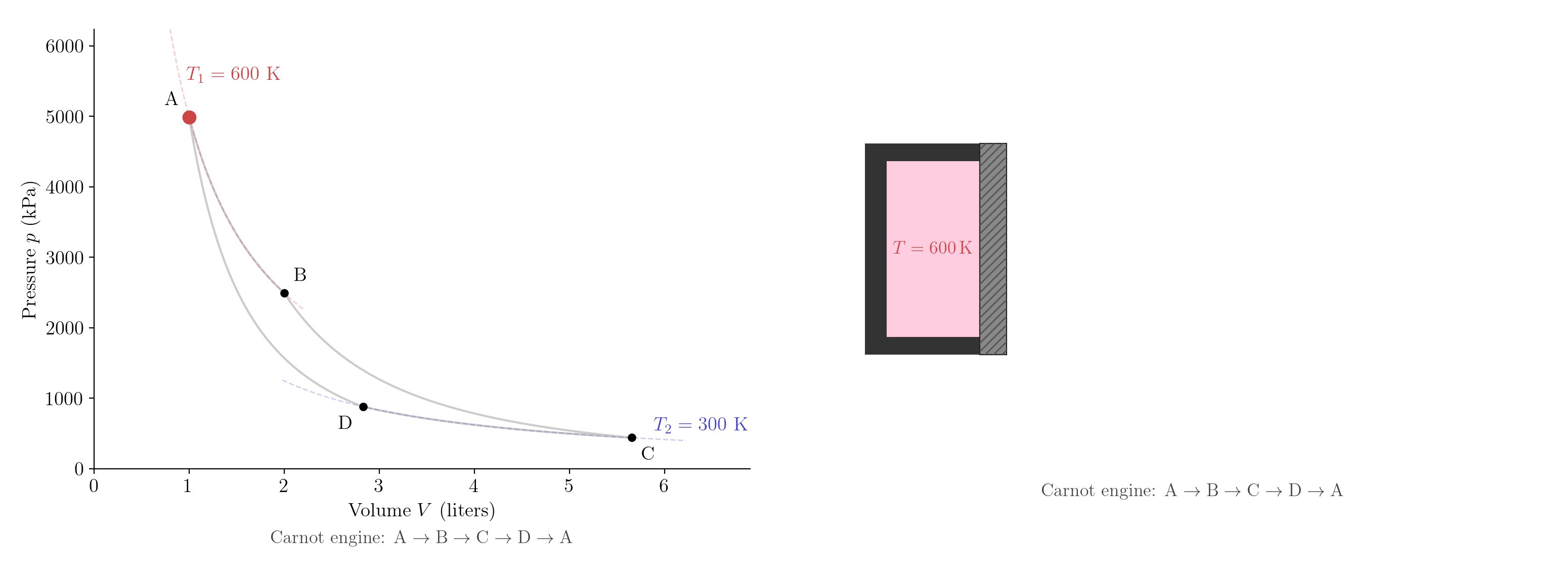
Dividing Equation 5.3 by Equation 5.5 gives \[\frac{V_B}{V_A} = \frac{V_C}{V_D}, \tag{5.6}\] so the expansion ratio is identical on both isothermal legs. Substituting Equation 5.6 into the ratio of Equation 5.4 to Equation 5.2: \[\frac{Q_2}{Q_1} = \frac{T_2 \ln(V_C/V_D)}{T_1 \ln(V_B/V_A)} = \frac{T_2}{T_1}. \tag{5.7}\] The net work delivered is \(W = Q_1 - Q_2\), so the efficiency of the Carnot engine is \[\eta^{\rm C} = \frac{W}{Q_1} = 1 - \frac{Q_2}{Q_1} = 1 - \frac{T_2}{T_1}. \tag{5.8}\]
A remarkable feature: \(\eta^{\rm C}\) depends only on \(T_1\) and \(T_2\), not on the amount of gas and not on the expansion ratio.
5.6 Characterization of cyclic machines working between two reservoirs
This section is supplementary and will not be covered in lecture.
The Second Law does not merely prohibit certain processes: it also constrains which energy flows are possible in a cyclic machine operating between two reservoirs. The following result gives a complete classification: only five types of energy flow are consistent with the Second Law, and they reduce in practice to two useful devices (heat engines and refrigerators), one trivial device (a dissipator), and one degenerate case (spontaneous heat flow with no work).
C 5.2 Consider a cyclic machine that exchanges heat with two reservoirs at different temperatures and work with the environment with the sign conventions of Figure 5.2 (for \(n=2\)). With no loss of generality, we assume \(\theta_1 > \theta_2\). Only the following energy flows are physically possible:
The machine does work on the surroundings, it absorbs heat from the hot reservoir and it releases heat to the cold reservoir, i.e. \(W>0\), \(Q_1>0\) and \(Q_2<0\). In this case, the machine is called a heat engine.
The machine extracts work from the surroundings, it absorbs heat from the cold reservoir and it releases heat to the hot reservoir, i.e. \(W<0\), \(Q_1<0\) and \(Q_2>0\). In this case, the machine is called a refrigerator or heat pump.
The machine extracts work from the surroundings, it releases heat to both reservoirs, i.e. \(W<0\), \(Q_1 \le 0\) and \(Q_2 \le 0\) with the condition that at least one between \(Q_1\) and \(Q_2\) is non-vanishing. In this case, the machine is just a dissipator which converts work into heat completely, but dumps heat into one or two reservoirs.
The machine extracts work from the surroundings, it absorbs heat from the hot reservoir and it releases heat to the cold reservoir, i.e. \(W<0\), \(Q_1 > 0\) and \(Q_2 < 0\). In this case, the machine is just a dissipator which converts work into heat completely, adds it to the heat absorbed from the hot reservoir and dumps it into the cold reservoir.
The machine does no work, it absorbs heat from the hot reservoir and it releases heat to the cold reservoir, i.e. \(W=0\), \(Q_1 \ge 0\) and \(Q_2 \le 0\). In this case the machine does not really do anything: heat is transferred from the hot to the cold reservoir as in the case of spontaneous heat flow.
5.6.1 Proof of statement
We proceed now to prove this statement. We will treat separately the three cases: \(W=0\), \(W<0\) and \(W>0\), which clearly cover all possibilities. We also notice that the First Law implies \(W = Q_1 + Q_2\) irrespectively of the signs of work and heat.
Case \(W=0\) (i.e. the machine does no work).
Thanks to the First Law \(Q_2 = -Q_1\). If \(Q_1 < 0\), then \(Q_2 > 0\) and the machine transfers heat from the colder reservoir to the hotter reservoir without any other effect on the surroundings. This is in flat contradiction with the Second Law (Principle 5.1). Therefore, one must have \(Q_1 \ge 0\) which implies \(Q_2 \le 0\), i.e. point 5 is realized.
Case \(W>0\) (i.e. the machine does work on the surroundings).
We want to prove by contradiction that \(Q_2 < 0\). The proof has the following structure: assume the negation of the thesis, construct a new cyclic machine and show that the new machine violates the Second Law.
Assumption. Assume that \(Q_2 \ge 0\).
Construction. After one cycle of the machine, place the two reservoirs in thermal contact until heat \(Q_2 \ge 0\) is transferred from the hot reservoir to the cold reservoir. The new machine is defined by the execution of the two operations in sequence. Notice that the new machine is cyclic because the physical system underlying in the combined machine is the same as the one underlying the original machine. The system returns to its original status after one cycle.
Contradiction. The combined machine, absorbs heat \(Q_1+Q_2=W>0\) from the hot reservoir, it dumps no heat into the cold reservoir and does work \(W>0\) on the surroundings. This machine is in contradiction with Kelvin’s statement (Consequence 5.1).
We have proved that \(Q_2 < 0\). Since \(Q_1 = W - Q_2\), \(W >0\) and \(-Q_2 >0\), it follows that \(Q_1 > 0\) i.e. point 1 is realized.
Case \(W<0\) (i.e. the machine extracts work from the surroundings).
In this case, the only restriction comes from the First Law and the Second Law is immaterial. In fact, \(W = Q_1 + Q_2 < 0\) implies that at least one between \(Q_1\) and \(Q_2\) must be (strictly) negative. The following possibilities are given: \(Q_1\) is negative and \(Q_2\) can have any sign i.e. either point 2 or 3 is realized, \(Q_1\) vanishes and \(Q_2\) is negative i.e. point 3 is realized, \(Q_1\) is positive and \(Q_2\) is negative i.e. point 4 is realized.
5.7 Problems
Problem 5.1 For each of the following processes, (i) explicitly describe the system and the surroundings; (ii) classify the process as reversible or irreversible; (iii) for irreversible processes, describe what would happen if one were to attempt to retrace the same sequence of intermediate states in reverse order, and specify whether the system, the surroundings, or both would not return to their initial state.
A gas is compressed extremely slowly in a piston-cylinder system. The piston experiences sliding friction against the cylinder wall. The gas is in thermal contact with a reservoir at temperature \(T\).
Two metal blocks, initially at temperatures \(T_1 \neq T_2\), are brought into thermal contact (and thermally isolated from everything else) and allowed to reach thermal equilibrium with each other.
A gas in thermal contact with a reservoir at temperature \(T\) is allowed to expand quasi-statically against a frictionless piston from volume \(V_1\) to \(V_2 > V_1\).
A paddle wheel submerged in a liquid is slowly driven by a hand crank. The liquid is in thermal contact with a reservoir at temperature \(T\).
An ideal gas in a thermally insulated cylinder is compressed quasi-statically from \(V_1\) to \(V_2 < V_1\) by a frictionless piston.
Problem 5.2 For each of the following processes, (i) explicitly describe the system and the surroundings; (ii) classify the process as reversible or irreversible; (iii) for irreversible processes, describe what would happen if one were to attempt to retrace the same sequence of intermediate states in reverse order, and specify whether the system, the surroundings, or both would not return to their initial state.
An ideal gas expands freely in a vacuum (a rigid, thermally insulated container with a removable partition).
Two ideal gases of different chemical species, which are initially at the same temperature \(T\) and the same pressure \(p\) in two chambers of equal volume separated by a partition, mix after the partition is removed.
A gas in thermal contact with a reservoir at temperature \(T\) is compressed by a frictionless piston so rapidly that the gas never reaches equilibrium during the compression.
An electric current is passed through an electrical resistor immersed in a liquid (a rigid container that is initially in thermal contact with a reservoir at temperature \(T\)); the switch is turned off, and the liquid is then allowed to reach thermal equilibrium with the reservoir again.
An ideal gas expands quasi-statically against a frictionless piston without heat exchange (the container is thermally insulated) from \(V_1\) to \(V_2 > V_1\).
Problem 5.3 A cyclic machine exchanges heat with two reservoirs at temperatures \(\theta_1 > \theta_2\) and exchanges net work with the surroundings (sign convention of Figure 5.2): \(Q_i\) positive means heat absorbed by the machine from reservoir \(i\), and \(W\) positive means work done by the machine on the surroundings. For each of the following cases, (i) compute the missing quantity using the First Law, (ii) classify the machine as a heat engine, a refrigerator, a dissipator (work is consumed and dissipated as heat into one or both reservoirs), or a device that merely transfers heat spontaneously from hot to cold without exchanging work, and (iii) redraw the energy flow diagram with \(|Q_1|\), \(|Q_2|\), \(|W|\) as positive quantities and arrows pointing in the physical direction.
- \(Q_1 = +100\ \mathrm{J}\), \(Q_2 = -40\ \mathrm{J}\), \(W = ?\)
- \(Q_1 = -50\ \mathrm{J}\), \(Q_2 = +30\ \mathrm{J}\), \(W = ?\)
- \(Q_1 = -20\ \mathrm{J}\), \(Q_2 = -30\ \mathrm{J}\), \(W = ?\)
- \(Q_1 = +80\ \mathrm{J}\), \(Q_2 = -80\ \mathrm{J}\), \(W = ?\)
Problem 5.4 Like Problem 5.3, with:
- \(Q_1 = +200\ \mathrm{J}\), \(Q_2 = -150\ \mathrm{J}\), \(W = ?\)
- \(Q_1 = +60\ \mathrm{J}\), \(Q_2 = -100\ \mathrm{J}\), \(W = ?\)
- \(Q_1 = -80\ \mathrm{J}\), \(Q_2 = +60\ \mathrm{J}\), \(W = ?\)
- \(Q_1 = 0\), \(Q_2 = -50\ \mathrm{J}\), \(W = ?\)
Problem 5.5 A Carnot engine operates between reservoirs at \(T_1 = 600\ \mathrm{K}\) and \(T_2 = 300\ \mathrm{K}\). In one cycle, it absorbs \(Q_1 = 1.20\ \mathrm{kJ}\) from the hot reservoir.
Compute the thermal efficiency \(\eta\).
Compute the net work \(W\) delivered per cycle.
Compute the heat \(Q_2\) released to the cold reservoir.
If the engine is to deliver a mechanical power of \(1.0\ \mathrm{kW}\), how many cycles per second must it execute?
Problem 5.6 A Carnot engine operates between reservoirs \(T_1 = 500\ \mathrm{K}\) and \(T_2 = 200\ \mathrm{K}\). In one cycle, it delivers \(W = 800\ \mathrm{J}\) of work to the surroundings.
Compute the thermal efficiency \(\eta\).
Compute the heat \(Q_1\) absorbed from the hot reservoir.
Compute the heat \(Q_2\) released to the cold reservoir.
If the engine is to deliver a mechanical power of \(5.0\ \mathrm{kW}\), how many cycles per second must it execute?
Problem 5.7 A Carnot engine uses \(n = 0.50\ \mathrm{mol}\) of a monatomic ideal gas (\(\gamma = 5/3\)) and operates between reservoirs at \(T_1 = 400\ \mathrm{K}\) and \(T_2 = 300\ \mathrm{K}\). In state A, the volume is \(V_A = 5.0\ \mathrm{L}\), and in state B (end of isothermal expansion at \(T_1\)), the volume is \(V_B = 10.0\ \mathrm{L}\).
Compute \(Q_1\) absorbed from the hot reservoir on leg A \(\to\) B.
Apply the adiabatic relation to leg B \(\to\) C to find \(V_C\), and to leg D \(\to\) A to find \(V_D\). Verify that \(V_B / V_A = V_C / V_D\).
Compute \(Q_2\) released to the cold reservoir on leg C \(\to\) D.
Compute the work done by the gas on each of the four legs, and the net work \(W\) per cycle. Verify that \(W / Q_1 = 1 - T_2/T_1\).
Problem 5.8 A Carnot engine uses \(n = 1.0\ \mathrm{mol}\) of a diatomic ideal gas in the rotational plateau (\(\gamma = 7/5\)) and operates between reservoirs at \(T_1 = 500\ \mathrm{K}\) and \(T_2 = 350\ \mathrm{K}\). In state A, the volume is \(V_A = 2.0\ \mathrm{L}\), and the isothermal expansion at \(T_1\) has an expansion ratio of \(V_B / V_A = 3\).
Compute \(Q_1\).
Apply the adiabatic relation to leg B \(\to\) C to find \(V_C\), and to leg D \(\to\) A to find \(V_D\). Verify that \(V_B / V_A = V_C / V_D\).
Compute \(Q_2\).
Compute the work done by the gas on each of the four legs, and the net work \(W\) per cycle. Verify that \(W / Q_1 = 1 - T_2/T_1\).
Problem 5.9 A reversible Carnot refrigerator extracts heat from a freezer compartment at \(T_2 = 260\ \mathrm{K}\) and releases heat to a kitchen at \(T_1 = 300\ \mathrm{K}\). To keep the freezer cold, it must extract heat at a rate of \(\dot Q_2 = 500\ \mathrm{W}\).
The coefficient of performance of a refrigerator is defined as \[ \mathrm{COP}_{\rm R} = \frac{Q_2}{W} , \tag{5.9}\] where \(Q_2\) is the heat extracted from the cold reservoir and \(W\) is the work consumed, both per cycle.
Compute \(\mathrm{COP}_{\rm R}\) for the Carnot refrigerator, and express it as a function of \(T_1\) and \(T_2\) alone.
Compute the minimum compressor power \(\dot W\) required to maintain \(\dot Q_2 = 500\ \mathrm{W}\).
Compute the rate \(\dot Q_1\) at which heat is dumped into the kitchen.
A real (irreversible) refrigerator with \(\mathrm{COP}_{\rm R} = 3\) is used instead. By what factor does the required compressor power increase?
Problem 5.10 A reversible Carnot heat pump heats a house at \(T_1 = 295\ \mathrm{K}\) by extracting heat from the outside air at \(T_2 = 270\ \mathrm{K}\). The house requires heat at a rate of \(\dot Q_1 = 10\ \mathrm{kW}\).
The coefficient of performance of a heat pump is defined as \[ \mathrm{COP}_{\rm HP} = \frac{Q_1}{W} , \tag{5.10}\] where \(Q_1\) is the heat transferred to the hot reservoir and \(W\) is the work consumed, both per cycle.
Compute \(\mathrm{COP}_{\rm HP}\) for the Carnot heat pump, and express it as a function of \(T_1\) and \(T_2\) alone. Verify the identity \(\mathrm{COP}_{\rm HP} = \mathrm{COP}_{\rm R} + 1\).
Compute the electrical power \(\dot W\) consumed by the heat pump.
Compare with an electric resistive heater that consumes \(\dot W' = 10\ \mathrm{kW}\) of electrical power and converts it directly into heat: by what factor is the heat pump more economical?
During a cold snap, the outdoor temperature drops to \(T_2 = 250\ \mathrm{K}\), while the house and the required heating capacity remain unchanged. By what factor does \(\dot W\) increase compared to part (b)?
Problem 5.11 (More demanding.) The Stirling cycle uses \(n\) moles of an ideal gas with constant adiabatic index \(\gamma\) as the working substance. It is a quasi-static cycle consisting of four legs in the \((V,p)\) plane: an isothermal expansion at \(T_1\) from \(V_A\) to \(V_B > V_A\) (A \(\to\) B), an isochoric cooling at \(V_B\) from \(T_1\) to \(T_2 < T_1\) (B \(\to\) C), an isothermal compression at \(T_2\) from \(V_B\) to \(V_A\) (C \(\to\) D), and isochoric heating at \(V_A\) from \(T_2\) to \(T_1\) (D \(\to\) A). In particular, \(V_C = V_B\) and \(V_D = V_A\).
Sketch the cycle in the \((V,p)\) plane.
Compute the heat \(Q\) exchanged by the gas on each of the four legs, taking care of signs. Identify the legs where heat is absorbed (\(Q > 0\)) and the legs where heat is released (\(Q < 0\)).
Compute the net work \(W\) done by the gas per cycle.
Define the thermal efficiency as \(\eta_{\rm S} = W / Q_{\rm in}\), where \(Q_{\rm in}\) is the total heat absorbed by the gas (summed over the legs where \(Q > 0\), including isochoric heating). Show that \[ \eta_{\rm S} = \frac{(T_1 - T_2)\ln(V_B/V_A)}{T_1 \ln(V_B/V_A) + (c_V/R)(T_1 - T_2)} < 1 - \frac{T_2}{T_1} . \] The right-hand side is the Carnot efficiency \(\eta^{\rm C}\) between the same two temperatures (see Equation 5.8). The significance of the inequality \(\eta_{\rm S} < \eta^{\rm C}\) will become clear in the next lecture, where Carnot’s theorem identifies \(\eta^{\rm C}\) as an upper bound for any cyclic engine operating between two reservoirs at \(T_1\) and \(T_2\).
Explain why this does not contradict the Carnot cycle discussed in this lecture. Hint: how many different temperatures does the gas come into thermal contact with during a Stirling cycle?
Problem 5.12 (More demanding.) The Otto cycle is the idealised thermodynamic cycle of a spark-ignition engine. It uses \(n\) moles of an ideal gas with constant adiabatic index \(\gamma\) as the working substance. It is a quasi-static cycle consisting of four legs in the \((V,p)\) plane: an adiabatic compression from \(V_A\) to \(V_B < V_A\) (A \(\to\) B), an isochoric heating at \(V_B\) (B \(\to\) C, modeling fuel combustion), an adiabatic expansion from \(V_B\) to \(V_A\) (C \(\to\) D), and an isochoric cooling at \(V_A\) back to the initial state (D \(\to\) A). Define the compression ratio \(r = V_A / V_B > 1\).
Sketch the cycle in the \((V,p)\) plane.
Compute the heat \(Q\) exchanged by the gas on each of the four legs. Identify the legs on which heat is absorbed and released.
Use the adiabatic relations for the legs A \(\to\) B and C \(\to\) D to show that \[ \frac{T_D - T_A}{T_C - T_B} = r^{1-\gamma} . \]
Show that the thermal efficiency \(\eta_{\rm O} = W/Q_{\rm in}\) depends only on the compression ratio and the adiabatic index: \[ \eta_{\rm O} = 1 - r^{1-\gamma}. \] Evaluate \(\eta_{\rm O}\) for \(\gamma = 7/5\) and \(r = 8\).
Determine the minimum and maximum gas temperature \(T_{\min}\) and \(T_{\max}\) reached during the cycle. (Unlike the Carnot engine, the Otto cycle is not in contact with two reservoirs at fixed temperatures: the gas is heated and cooled along the isochores by external means.) Compare \(\eta_{\rm O}\) with the Carnot efficiency \(\eta^{\rm C} = 1 - T_{\min}/T_{\max}\) between the same two temperatures. The significance of the inequality \(\eta_{\rm O} < \eta^{\rm C}\) will become clear in the next lecture with the Carnot theorem.
Problem 5.13 (More demanding. Forward-looking: previews Carnot’s theorem.) A hypothetical cyclic engine \(X\) operates between two reservoirs \(T_1\) and \(T_2 < T_1\), absorbs \(Q_1^X > 0\) from the hot reservoir, releases work \(W^X > 0\) to the surroundings per cycle, and releases \(Q_2^X > 0\) to the cold reservoir. Assuming its efficiency exceeds the Carnot value: \[ \eta_X = \frac{W^X}{Q_1^X} > 1 - \frac{T_2}{T_1} = \eta^{\rm C} . \] Combine \(X\) with a reversible Carnot refrigerator operating between the same two reservoirs, such that the refrigerator consumes exactly the work \(W^X\) per combined cycle, which is supplied by \(X\).
Express, in terms of \(W^X\), \(T_1\), \(T_2\), the heat \(Q_1^{\rm R}\) released by the refrigerator into the hot reservoir and the heat \(Q_2^{\rm R}\) extracted from the cold reservoir per combined cycle.
Compute the net heat \(\Delta Q_1\) exchanged with the hot reservoir and the net heat \(\Delta Q_2\) exchanged with the cold reservoir, per combined cycle, and show that \(\Delta Q_1 < 0\) and \(\Delta Q_2 > 0\).
Show that the combined cyclic machine transfers heat from the cold reservoir to the hot reservoir without exchanging net work with the surroundings, which violates Clausius’s statement.
Conclude that for every cyclic engine operating between two reservoirs at \(T_1\) and \(T_2\), the efficiency satisfies \(\eta \leq \eta^{\rm C}\). This is the first part of Carnot’s theorem, which will be the subject of the next lecture.
Problem 5.14 (More demanding. Forward-looking: previews Carnot’s theorem.) Two reversible cyclic engines \(X\) and \(Y\) operate between the same two reservoirs, \(T_1\) and \(T_2 < T_1\). Suppose their efficiencies differ, with \(\eta_X > \eta_Y\).
Operate \(X\) as an engine and \(Y\) in reverse as a refrigerator (this is possible because \(Y\) is reversible). Scale the two so that the refrigerator \(Y\) consumes exactly the amount of work per combined cycle that a cycle of \(X\) delivers. Show, using the same argument as in Problem 5.13, that the combined cyclic machine violates Clausius’s statement.
Swap the roles of \(X\) and \(Y\) (i.e., assume \(\eta_Y > \eta_X\) instead) and repeat the argument to derive a contradiction with Clausius’s statement.
Conclude that \(\eta_X = \eta_Y\), i.e., all reversible engines operating between the same two reservoirs have the same efficiency, regardless of the working substance and the details of the cycle. This is the second half of Carnot’s theorem and forms the foundation for the construction of the absolute thermodynamic temperature scale (next lecture).
Problem 5.15 (More demanding. Forward-looking: previews entropy.) Consider one cycle of the Carnot engine of Problem 5.7 (\(n = 0.50\ \mathrm{mol}\) monatomic ideal gas, \(T_1 = 400\ \mathrm{K}\), \(T_2 = 300\ \mathrm{K}\), \(V_A = 5.0\ \mathrm{L}\), \(V_B = 10.0\ \mathrm{L}\)). For each leg \(i = 1, 2, 3, 4\), let \(Q_i\) be the heat absorbed by the gas on that leg (with sign: positive if absorbed, negative if released) and \(T_i\) be the temperature of the gas on that leg.
Argue that the adiabatic legs contribute zero to the sum \(\sum_i Q_i / T_i\).
Compute \(Q_1/T_1\) and \(Q_3/T_3\) numerically and verify that \[ \sum_{i=1}^{4} \frac{Q_i}{T_i} = 0 . \]
Show that this property holds for every Carnot engine, regardless of the working substance, the volumes \(V_A, V_B, V_C, V_D\), and the temperatures of the reservoirs. Hint: use Equation 5.7 and recall that the quantity \(Q_2\) defined in Equation 5.4 is the negative of the heat absorbed by the gas on the C \(\to\) D leg, according to the sign convention used in this problem.
In the next lecture, this result will be generalized to any reversible cycle: the integral \(\oint \delta Q / T\) vanishes around any reversible loop. Following the same logic that made \(U\) a state function (Lecture 2), this implies the existence of a new state function: the entropy \(S\), with \(dS = \delta Q_{\rm rev}/T\).
Problem 5.16 (More demanding. Forward-looking: previews the Clausius inequality.) An irreversible cyclic engine operates between two reservoirs \(T_1 = 500\ \mathrm{K}\) and \(T_2 = 300\ \mathrm{K}\). Per cycle, it absorbs \(Q_1 = 1.0\ \mathrm{kJ}\) from the hot reservoir and has a measured thermal efficiency of \(\eta = 0.30\). In this problem, \(Q_1\) and \(Q_2\) denote positive quantities (the sign convention for heat engines).
Compute the work \(W\) done per cycle and the heat \(Q_2\) released to the cold reservoir.
Compute the quantity \[ \Sigma = \frac{Q_1}{T_1} - \frac{Q_2}{T_2} . \] Is it positive, zero, or negative?
Show that for every cyclic engine with two reservoirs and efficiency \(\eta \leq \eta^{\rm C} = 1 - T_2/T_1\), the quantity \(\Sigma\) is non-positive, with equality holding if and only if \(\eta = \eta^{\rm C}\). (The assumption that every cyclic engine satisfies \(\eta \leq \eta^{\rm C}\) will be proven in the next lecture as the Carnot theorem.)
Compare with Problem 5.15. In the next lecture, the result \(\Sigma \leq 0\) will be generalized to any cyclic process as the Clausius inequality \(\oint \delta Q / T \leq 0\), with equality holding if and only if the cycle is reversible.
Note for instructors only — not examinable. The quantity plotted is not the thermodynamic entropy but a proxy: the normalised Shannon entropy of the binary left/right occupancy, \(\tilde S = -[f_L \ln f_L + f_R \ln f_R]/\ln 2\), where \(f_L\) and \(f_R = 1-f_L\) are the fractions of the \(N = 60\) simulated particles in the left and right halves at each frame. This quantity equals 0 when all particles are on one side and 1 when the split is 50/50. It is a coarse-grained proxy for the thermodynamic entropy change \(\Delta S = nR\ln 2\) (derived in Lecture 6 from the first \(T\,dS\) equation), and it fluctuates with amplitude \(\sim 1/\sqrt{N}\) because only a finite number of particles is used. The reverse phase is the exact time reversal of the forward simulation: at the frame of maximum expansion, all particle velocities are flipped and the simulation is continued for the same number of steps, so the particles retrace their trajectories exactly and spontaneously return to the left half.↩︎